
IIS Manufactures & Supplies Disc Spring DIN 2093
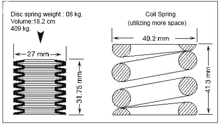
Disc Springs are conically formed angular discs, which are loaded in the axial direction. Disc Springs have a unique combination of high force in small space with customized deflection combinations.
IIS Disc Springs offer a well-developed solution to many engineering problems. Disc Springs can be used as single disc or arranged in stacks. A Disc Spring stack can consist of disc springs either used in Series or Parallel sets. Disc Springs are available with or without contact flats. Disc Springs are manufactured to DIN 2093 and designed as per DIN 2092. We have custom design program to assist our customers for their specific applications. Our group 1 & 2 Disc Springs are AUSTEMPERED, this method of heat treatment is particularly effective for high fatigue Disc Springs.
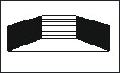
Stacked in parallel
Total Deflection=Deflection
of 1 disc
Total Load= Load on 1 disc X no.of discs.
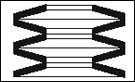
In Series
Total Deflection=
Deflection of 1 disc X no. of
discs in stack
Total Load =
Load on 1 disc
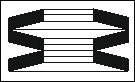
Parallel Series COMBINATIONS
It Can be designed to accommodate virtually any load or deflection and to obtain progressive characteristics
Advantages of Disc Springs:
1.No Deformation or Fatigue under normal loads.
2.High Energy Storage Capacity.
3.Long Service Life.
4.Stock keeping is minimized as the individual spring sizes can be combined universally.
5.Space Saving.
6.Largely Self-damping, giving good shock absorption and energy dissipation.
7.Efficient use of space and high spring force with small deflections.
8.Adaptable to stacking in numerous configurations.
9.Combination use as a modular spring element.
10.Low Maintenance cost & Greater Security
11.Low height/thickness ratio employed reduces stresses
Surface Technology & Coating Services
IIS offers a variety of coating services on all parts manufactured. List of coatings are available below. For other specific coating and applications
Please refer this link
List of Raw Materials for Disc Springs View Details
• Application And Selection Click Here
• Installation Setting & Stacking Click Here
• Symbols and Units Click Here
* Automotive & Engines
* Brakes & Clutches
* Dampers
* Hoists
* Machine Tools
* Shock Mounts
* Vibrators
Selection
a)
If the application involves large numbers of deflection cycles. i.e. "dynamic" application, or if the required forces or deflections are of a critical nature, we strongly recommend that you select from the range of Disc Springs that confirms to the DIN 2093 specification.
b)
From the range available, select the largest possible Disc Spring compatible with the desired characteristics. This will assist in maintaining the lowest possible stresses, thus enhancing the fatigue life. In case of stacked columns the greater deflection offered by the larger diameter springs will ensure the shortest possible stack length.
c)
For Static or dynamic application, select a Disc Spring that, at 75% of its total available deflection offers the maximum force and deflection required.
d)
As a result of manufacturing processes, residual tensile stresses occur at I, the upper inside diameter edge, which will revert to normal compressive stresses when the Disc Spring is deflected by up to approximately 15% of its total deflection.
DISC SPRING INSTALLATION, SETTING & STACKING
Installation:
a)
Dynamic applications, involving large numbers of deflection cycles, will require that in addition to hardened seating faces the guide surfaces must also be sufficiently hard to prevent excessive wear or "stepping". For both support washers and guide elements, a polished surface with hardness of 58HRC is sufficient, and case depth should be 0.60mm min.
b)
A most important aid to efficient and extended life of Disc Spring is the provision of some form of lubrication. For relatively low-duty Disc Spring application, a liberal application of suitable solid lubricant, (e .g. molybdenum-disulphide, grease), to the contact points and locating surfaces of the spring is adequate.

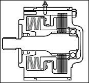
Disc Spring with Contract Flats and Reduced Thickness: For Disc
Springs with a thickness of more than 6mm, DIN 2093 specifies small contact surfaces at point I III in Addition to the rounded corners. These contact flats improve definition of the point of load application and reduce friction at the guide rod. Contact flat increase spring load which is to be compensated by a reduction in the thickness from 't' to 't'.
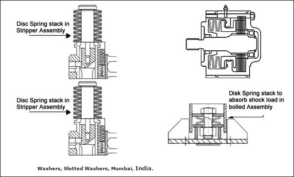
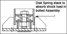
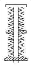
Stacking :
Series Stacking: The cumulative effect of bearing point friction of large numbers of Disc Springs stacked in series, can result in the Disc Springs at each end of the stack deflecting more than those in the center. In extreme cases this may result in over-compression and premature failure of the end springs. A “rule of thumb” is that the length of the stacked Disc Springs should not exceed a length approximately equal to 3 times the outside diameter of the Disc Spring.
Stack Length :
When stacking Disc Springs, effort should be made to keep the stacks as short as possible. Friction and other influences make a stack more uneven. It deflects more on the side of the loading. This effect usually can be neglected for a "normal" spring stack, but not for long stacks. If it is longer, the stack can be stabilized by dividing it with guide washers, which as a rule of thumb should have a thickness of at least one and a half times the guide diameter.
DISC SPRING : SYMBOLS & UNITS
Symbols and Units : Standard sizes available as per DIN 2093
Group Classification of Disc springs

In accordance with DIN 2093 Standard, Disc Springs are classified into 3 groups as given in the table:
| Group | Thickness of single disc in mm |
Single disc with Ground ends & reduced material thickness (t') |
|---|---|---|
| 1 | less than 1.25 | No |
| 2 | From 1.25 to 6 | No |
| 3 | Over 6 upto 14 | Yes |
Symbols and Units
| Symbol | Unit | Term |
|---|---|---|
| De | mm | Outside diameter |
| Do | mm | Inside diameter |
| E | mm | Mean diameter |
| F | N/mm2 | Modulus of elasticity |
| ho | N | Formed height |
| lo | mm | Free overall height of spring in its initial position |
| s | mm | Deflection of single disc |
| t | mm | Thickness of single disc |
| t1 | mm | Reduced thickness of single disc in the case of springs with ground ends (group 3) |
| µ | mm | Poisson's ratio |
| d OM,ol,oil, d III, &dIV, |
N/mm2 | Design stresses at the points designated OM, I, II, III, and IV (see figure) |
| ▲F | N | Relaxation |
DISC SPRINGS : Std Din 2093 ( IIS Disc Springs )
Complete List of all sizes available in ready stock can be Downloaded in a pdf format
| SERIES A | ||||||
|---|---|---|---|---|---|---|
| De h12 |
Di H12 |
t | H0 | lo | S (0.75ho) | F N |
| 8.0 | 4.2 | 0.4 | 0.2 | 0.60 | 0.15 | 210 |
| 10 | 5.2 | 0.5 | 0.25 | 0.75 | 0.19 | 329 |
| 12.5 | 6.2 | 0.7 | 0.3 | 1.00 | 0.23 | 673 |
| 16 | 8.2 | 0.8 | 0.3 | 1.10 | 0.23 | 813 |
| 18 | 9.2 | 1.0 | 0.4 | 1.4 | 0.30 | 1250 |
| 20 | 10.2 | 1.1 | 0.45 | 1.55 | 0.34 | 1530 |
| 22.5 | 11.2 | 1.25 | 0.5 | 1.75 | 0.38 | 1950 |
| 25 | 12.2 | 1.5 | 0.55 | 2.05 | 0.41 | 2910 |
| 31.5 | 16.3 | 1.75 | 0.7 | 2.45 | 0.53 | 3900 |
| 35.5 | 18.3 | 2.0 | 0.8 | 2.80 | 0.60 | 5190 |
| 40 | 20.4 | 2.25 | 0.9 | 3.15 | 0.68 | 6540 |
| 45 | 22.4 | 2.5 | 1.0 | 3.50 | 0.75 | 7720 |
| 50 | 25.4 | 3.0 | 1.1 | 4.10 | 0.83 | 12000 |
| 56 | 28.5 | 3.0 | 1.3 | 4.30 | 0.98 | 11400 |
| 63 | 31 | 3.5 | 1.4 | 4.90 | 1.05 | 15000 |
| 71 | 36 | 4.0 | 1.6 | 5.60 | 1.20 | 20500 |
| 80 | 41 | 5.0 | 1.7 | 6.70 | 1.28 | 33700 |
| 90 | 46 | 5.0 | 2.0 | 7.00 | 1.50 | 31400 |
| 100 | 51 | 6.0 | 2.2 | 8.20 | 1.65 | 48000 |
| 112 | 57 | 6.0 | 2.5 | 8.50 | 1.88 | 43800 |
| 125 | 64 | 8.0 | 2.6 | 10.60 | 1.95 | 85900 |
| 140 | 72 | 8.0 | 3.2 | 11.20 | 2.40 | 85300 |
| 160 | 82 | 10 | 3.5 | 13.50 | 2.63 | 139000 |
| 180 | 92 | 10 | 4.0 | 14.00 | 3.00 | 125000 |
| 200 | 102 | 12 | 4.2 | 16.2 | 3.15 | 183000 |
| 225 | 112 | 12 | 5.0 | 17 | 3.75 | 171000 |
| 250 | 127 | 14 | 5.6 | 19.6 | 4.20 | 249000 |
| SERIES B | ||||||
|---|---|---|---|---|---|---|
| De h12 |
Di H12 |
t | H0 | lo | S (0.75ho) | F N |
| 8.0 | 4.2 | 0.3 | 0.25 | 0.55 | 0.19 | 119 |
| 10 | 5.2 | 0.4 | 0.3 | 0.7 | 0.23 | 213 |
| 12.5 | 6.2 | 0.5 | 0.35 | 0.85 | 0.26 | 291 |
| 14 | 7.2 | 0.5 | 0.40 | 0.9 | 0.30 | 279 |
| 16 | 8.2 | 0.6 | 0.45 | 1.05 | 0.34 | 412 |
| 18 | 9.2 | 0.6 | 0.5 | 1.2 | 0.38 | 572 |
| 20 | 10.2 | 0.7 | 0.55 | 1.35 | 0.41 | 745 |
| 22.5 | 11.2 | 0.8 | 0.65 | 1.45 | 0.49 | 710 |
| 25 | 12.2 | 0.8 | 0.7 | 1.6 | 0.53 | 868 |
| 28 | 14.2 | 0.9 | 0.8 | 1.8 | 0.60 | 1110 |
| 31.5 | 16.3 | 1.0 | 0.9 | 2.15 | 0.68 | 1920 |
| 35.5 | 18.3 | 1.25 | 1.0 | 2.25 | 0.75 | 1700 |
| 40 | 20.4 | 1.25 | 1.15 | 2.65 | 0.86 | 2620 |
| 45 | 22.4 | 1.5 | 1.3 | 3.05 | 0.98 | 3660 |
| 50 | 25.4 | 1.75 | 1.4 | 3.4 | 1.05 | 4760 |
| 56 | 28.5 | 2.0 | 1.6 | 3.6 | 1.20 | 4440 |
| 63 | 31 | 2.0 | 1.75 | 4.25 | 1.31 | 7180 |
| 71 | 36 | 2.5 | 2.0 | 4.5 | 1.50 | 6730 |
| 80 | 41 | 2.5 | 2.3 | 5.3 | 1.73 | 10500 |
| 90 | 46 | 3.0 | 2.5 | 6.0 | 1.88 | 14200 |
| 100 | 51 | 3.5 | 2.8 | 6.3 | 2.10 | 13100 |
| 112 | 57 | 3.5 | 3.2 | 7.2 | 2.40 | 17800 |
| 125 | 64 | 4.0 | 3.5 | 8.5 | 2.63 | 30000 |
| 140 | 72 | 5.0 | 4.0 | 9.0 | 3.00 | 27900 |
| 160 | 82 | 6.0 | 4.5 | 10.5 | 3.38 | 41100 |
| 180 | 92 | 6.0 | 5.1 | 11.1 | 3.83 | 37500 |
| 200 | 102 | 8.0 | 5.6 | 13.6 | 4.20 | 76400 |
| 225 | 112 | 8.0 | 6.5 | 14.5 | 4.88 | 70800 |
| 250 | 127 | 10 | 7.0 | 17 | 5.25 | 119000 |
| SERIES c | ||||||
|---|---|---|---|---|---|---|
| De h12 |
Di H12 |
t | H0 | lo | S (0.75ho) | F N |
| 8.0 | 4.2 | 0.2 | 0.25 | 0.45 | 0.19 | 39 |
| 10 | 5.2 | 0.25 | 0.3 | 0.55 | 0.23 | 58 |
| 12.5 | 6.2 | 0.35 | 0.45 | 0.8 | 0.34 | 152 |
| 14 | 7.2 | 0.35 | 0.45 | 0.8 | 0.34 | 123 |
| 16 | 8.2 | 0.35 | 0.4 | 0.9 | 0.38 | 155 |
| 18 | 9.2 | 0.4 | 0.45 | 1.05 | 0.45 | 214 |
| 20 | 10.2 | 0.50 | 0.65 | 1.15 | 0.49 | 254 |
| 22.5 | 11.2 | 0.60 | 0.80 | 1.40 | 0.60 | 425 |
| 25 | 12.2 | 0.70 | 0.90 | 1.60 | 0.68 | 601 |
| 28 | 14.2 | 0.80 | 1.00 | 1.80 | 0.75 | 801 |
| 31.5 | 16.3 | 0.80 | 1.05 | 1.85 | 0.75 | 687 |
| 35.5 | 18.3 | 0.90 | 1.15 | 2.05 | 0.86 | 831 |
| 40 | 20.4 | 1.00 | 1.30 | 2.30 | 0.98 | 1020 |
| 45 | 22.4 | 1.25 | 1.60 | 2.85 | 1.20 | 1890 |
| 50 | 25.4 | 1.25 | 1.60 | 2.85 | 1.20 | 1550 |
| 56 | 28.5 | 1.50 | 1.95 | 3.45 | 1.45 | 2620 |
| 63 | 31 | 1.80 | 2.35 | 4.15 | 1.76 | 4240 |
| 71 | 36 | 1.80 | 2.60 | 4.60 | 1.95 | 5140 |
| 80 | 41 | 2.25 | 2.95 | 5.20 | 2.21 | 6610 |
| 90 | 46 | 2.5 | 3.20 | 5.70 | 2.40 | 7680 |
| 100 | 51 | 2.70 | 3.50 | 6.20 | 2.63 | 8610 |
| 112 | 57 | 3.00 | 3.50 | 6.90 | 2.93 | 10500 |
| 125 | 64 | 3.50 | 3.90 | 8.00 | 3.38 | 15400 |
| 140 | 72 | 3.80 | 4.90 | 8.70 | 3.68 | 17200 |
| 160 | 82 | 4.30 | 5.60 | 9.90 | 4.20 | 21800 |
| 180 | 92 | 4.80 | 6.20 | 11.00 | 4.65 | 26400 |
| 200 | 102 | 5.50 | 7.00 | 12.50 | 5.25 | 36100 |
| 225 | 112 | 6.50 | 7.10 | 13.60 | 5.33 | 44600 |
| 250 | 127 | 7.00 | 7.80 | 14.80 | 5.85 | 50500 |
Tolerances:
As cost is a major consideration, springs must be produced in the most economical manner. Specified tolerances, therefore, should be generous enough to permit the fabrication of acceptable springs by ordinary production methods. Also, it is wise to apply tolerances only to functional requirements and dimensions. This practice gives the spring maker an opportunity to make adjustments to make compensate for the allowable variations present in the size and mechanical properties of all spring materials. Another recommendation for the product designers: If the standard drawing forms have tolerance boxes for machined dimensions they are almost sure to be impractical for springs. Delete them and apply realistic tolerances to the mandatory spring requirements.
Disc Spring Tolerances:
The following maximum deviations are laid down in DIN 2093. They are valid for all Disc Springs as per the DIN and our works standards. In general IIS also applies these tolerances to special sizes, however, if they deviate greatly from the DIN, wider tolerances must be specified.
This applies to our ball-bearing Disc Springs. If closer tolerances are required than those tolerances in DIN 2093, please consult us.
Thickness Tolerances
| Group | t or t' (mm) | Tolerance for t (mm) |
|---|---|---|
| 1 | 0.2 to 0.6 >0.6 to <1.25 |
+0.02/-0.06 +0.03/-0.09 |
| 2 | 1.25 to 3.8 >3.8 to 6.0 |
+0.04/-0.12 +0.05/-0.15 |
| 3 | >6.0 to 14.0 | +0.10/-0.10 |
Thickness Tolerances
| Group | t | Tolerance for t (mm) |
|---|---|---|
| 1 | <1.25 | +0.25.0 - 7.5 |
| 2 | 1.25 to 3.0 >3.0 to 6.0 |
+0.15 - 7.5 |
| 3 | >6.0 to 14.0 | + 5.0 |
To ensure the specified spring forces, DIN 2093 allows the overall height tolerance to be slightly exceeded.
Theoretical vs Measured Characteristic of a Disc Spring
The characteristic of the individual Disc Spring is non-linear. Its shape depends on the ratio ho/t. At the lower portion of the deflection range the characteristic in practice depart slightly from the theoretical. When S/ho>0.75 the characteristic in practice again departs increasingly from the theoretical because the Disc Springs roll upon one another or upon the supporting surface and this leads to a continuous shortening of the lever arm. For this reason, the spring force is only indicated at Ss=0.75 ho in DIN 2093.